Monday, December 31, 2007

Extarct system backup to IBM system p5


Can take a system backup using AIX command mksysb.The mksysb command ensures that the block size is 512 when these images are created.Bootable mksysb tapes comprise the following images:Boot image,BOS Installation/Maintenance image,Table of contents image,System backup image.
  • Creates a complete backup of rootvg.
  • If image is saved to tape, the tape is bootable and can be used to completely clone the machine.
  • If you need to restore a mksysb image to a machine of a different architecture than the one you made the image on (e.g., POWER-2 to PowerPC), you must use a special clone disk.
Restoring a file from the tape

Follow these steps to restore a file from the Tape.

  1. Be sure the tape block size is 512 by entering the following command: # lsattr -E -l rmt0.

    If the block size is not correct, use the following command to set it to 512: # chdev -l rmt0 -a block_size=512.

  2. Make sure the tape is rewound. If the tape is not rewound, enter the following command: # tctl -f /dev/rmt0 rewind
  3. Extract the necessary files by entering: # restore -xvq -s2 -f /dev/rmt0.1.filename
    Note: The filename should be the full path, and always preceded with a . (dot character), such as ./tapeblksz.
  4. Rewind the tape by entering: # tctl -f /dev/rmt0 rewind
  5. Change the block size back to its original value, if necessary.
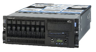
I have restore a backup from a tape for Omega line server(system p5 machine )

Avaya IP soft phone


IP Softphone works the same way as an IP phone. IP Softphone makes it easy to place and receive phone calls from your PC or laptop, making it ideal for working from any location with an internet connection – such as home office, a hotel, coffee shop, or even an airport.
It offers simple Graphical User Interfaces (GUIs) and integrates well with Microsoft desktop applications such as Outlook and Internet Explorer, enabling click to dial and screen pops. There are options to add Instant Messaging and Presence as well as videoconferencing for enhanced collaboration capabilities. IP Softphone links with your deskphone so that calls to you will ring at your deskphone and PC.

Call center- proof of concept


The system is designed with a centralized server where all station registration and call control happens. There are distributed gateways across various geographically dispersed locations to support TDM connectivity and media resource distribution.
Survivability is built for each remote location in case of a link failure or central location failure. The system is a fully redundant server system with a backup option connected at DR site. The main server is a duplicated server with active and hot standby servers where fail over happens seamlessly.
The system will demonstrate two separate sites. Main Site consists of a S8720 Media server and G650 Media Gateway. Remote Site will have another G650 Media Gateway controlled by the Main Server.Additionally the Remote site will have a S8300 Media Server and housed in a G700 Media Gateway.
The stations physically distributed between two sites will be administered on the Primary Server located Main Site. Avaya Communication Manager allows the customer to create the dial plan using from three to seven digits.

Upgrading Avaya IP Phones


IP telephone TFTP installation

Download TFTP application from Avaya web site and run the installer.After installing the application run it and enter to system set up(ctrl+U).In the outbound menu enter the directory where you will place the IP Telephone files.
IP phone working with DHCP server and TFTP server

When an Avaya phone powers up, it shows a test pattern on the phone's display and the hold lamp is lit.The phone requests an IP address from the DHCP server on the native (data) VLAN. The DHCP server offers an address and also a string of configuration information that among other things, tells the phone which VLAN to use.

The phone then reboots and begins tagging Ethernet frames with the proper VLAN information. The phone will display "DHCP xxx."

Next, the phone requests an address from the DHCP server, this time on the voice VLAN. The DHCP server responds with an IP address on the voice VLAN, and additional configuration information including the address of the TFTP server and the C-LAN (IP PBX interface) card. The phone will display "DHCP."

Now the phone connects to the TFTP server, downloads configuration information and firmware upgrade (if needed). The phone will display "TFTP server a.b.c.d."

Finally, the phone will connect to the C-LAN card and attempt to register with the Communication Manager (IP PBX application). If the DHCP server offered several C-LAN addresses, the phone will try them in order until registration is successful. During this process, the phone will display "Discovering…"

When the phone connects to the PBX, it will either display the extension and time, or it will display the prompt "Ext=", meaning it is waiting to be told what extension to use. In either case, the phone has successfully completed the boot process. From a networking perspective, everything is working properly.
Connecting NICE Logger


I installed a NICE logger for standard charted bank.NICE logger is an application running on top of windows server 2003.Here we used it for call canter integration.We use NICE logger to analyze inbound and outbound calls transfers and record calls.We used SQL2000 server as the database.

NiceLog Logger serves as the system voice capture and call logging unit. It supports a wide range of telephony interfaces including analog, digital, E1/T1, BT Megalink and SCSA.The High Density Logger utilizes NICE’s leading-edge board technology for stereo recording, separating customer and agent voices to make extended audio analysis (including word spotting, emotion detection and talk analysis) possible in a single unit.

Connecting Analog Lines
Analog lines are connected to the ALI PCI port.When we are patching these to the punch down box(KRONE module) lines sent through logger ports with out terminating them.I terminate the open-leads cable on the Logger side with a 50-pin male connector. The 50-pin
male connector is then plugged into the connector on the ALI PCI board on the rear panel of the
Logger. Each ALI PCI board in the Logger can receive up to 24 analog inputs.

Connecting Digital lines

Digital lines are connected to the NATI PCI port.Here also we patch cables as same as above.Passive digital recording is mainly used for total or all channel recording of digital extensions.When implementing passive digital recording, a passive coupler is required. This ensures that theconnection to the Logger does not interfere with the digital phone set or switch.